Screening layers · GCT, GDLT, GVOT, GOBT
Screening the joint: semi-conductive tube, GDLT and GVOT
GDLT 30/11 recovers 30 mm to 11 mm across a 5.0 mm wall. That one wall reads 1 × 10¹⁴ Ohm.cm on the bore and 1 × 10³ Ohm.cm on the face.
- Eight GDLT codes, 30/11 to 120/45, recovered wall 5.0 to 7.5 mm, all to 36 kV.
- Six GVOT sizes on the datasheet, six different ones on the web page, a third set printed on the product itself.
- No dimensional chart exists for the semi-conductive tube. GCT 30/10 to GCT 180/55 is the whole published record.
Why anything sits across the cutback at all
Cut the screen back on an MV core and the earthed surface stops at a hard edge. The manufacturer names the place in its own words: its stress control tube exists to control the high electrical stress present at insulation-screen terminals. Three of the four parts below are extruded to lie across that edge. The fourth deals with what leaks out of the paper behind it.
One edge, two jobs. At a termination the core goes out into air and the field has to be graded down over a length. At a straight-through joint the screen has to be rebuilt so it stays continuous past the connector. This page is the second job. The first — and the discrete stress control tube that does it, Insultube-Stress, radiation cross-linked, standard black, -40 °C to 100 °C, fully recovered at 130 °C — belongs to the termination reference.
Size these the way you size any tube here. D min. must clear the diameter over the built-up insulation; d max. must close below the cable's own screen where the tube lands. On GDLT the two ends are closer together than the codes suggest: 65/27 works out at 2.4:1 and 100/35 at 2.9:1, so nothing in the range is a 3:1 part.
Four parts, four different jobs at the same edge
INSULTUBE Semi-Conductive
Thermally stabilised cross-linked semi-conductive polymer. It screens the built-up insulation over the connector in plastic and paper-insulated joints to 36 kV. Series GCT 30/10 to GCT 180/55, with nothing published between those two ends.
GDLT double layer
One co-extruded tube: insulating inner layer, semi-conductive outer layer, for straight-through joints to 36 kV. Eight codes, GDLT 30/11 to GDLT 120/45, recovered wall 5.0 to 7.5 mm. Standard colour black/red.
GVOT varistor sleeve
Cross-linked polyolefin with an integrated varistor stress-control system, plus a sealant that leaves a moisture-proof seal. Six sizes, recovered wall 2.5 to 3.0 mm. Supplied inside a Gala termination to 36 kV rather than bought loose.
GOBT oil barrier
Six sizes, GOBT 30/10 to GOBT 115/34, wall toleranced to ±10%. It goes over PILC to stop the impregnating compound leaving the paper at a cut end, and it adds insulation to 36 kV.
GDLT selection chart
| Gala code | D min. (mm) | d max. (mm) | T (mm) |
|---|---|---|---|
| GDLT 30/11 | 30 | 11 | 5.0 ± 0.3 |
| GDLT 35/13 | 35 | 13 | 5.0 ± 0.3 |
| GDLT 45/16 | 45 | 16 | 5.0 ± 0.3 |
| GDLT 55/20 | 55 | 20 | 5.0 ± 0.3 |
| GDLT 65/27 | 65 | 27 | 5.0 ± 0.3 |
| GDLT 85/30 | 85 | 30 | 7.5 ± 0.3 |
| GDLT 100/35 | 100 | 35 | 7.0 ± 0.3 |
| GDLT 120/45 | 120 | 45 | 7.0 ± 0.4 |
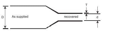
D is supplied ID, d is recovered ID, T is recovered wall. The wall does not climb with the bore: GDLT 85/30 is the thickest at 7.5 mm and both larger codes step back below it. Figures from the manufacturer's Double Layer Tube datasheet; set them against the other series on the size chart.
The only two rows where the layers differ
| Property | Inner insulation layer | Outer semi-conductive layer | Test method |
|---|---|---|---|
| Dielectric strength | 20 kV/mm (min.) | N/A | ASTM D149 |
| Volume resistivity | 1 × 10¹⁴ Ohm.cm (min.) | 1 × 10³ Ohm.cm (min.) | ASTM D257 |
Eleven orders of magnitude across one co-extruded wall. That gap is the whole product, and these are the only rows on the sheet where the two columns diverge.
GDLT properties, identical on both layers
| Property | Both layers | Test method |
|---|---|---|
| Tensile strength | 12 MPa (N/mm²) (min.) | ASTM D638 |
| Ultimate elongation | 300 % (min.) | ASTM D638 |
| Longitudinal change | -10 % (max.) | ASTM D2671 |
| Hardness | 50 ± 3 Shore D | ASTM D2240 |
| Water absorption | 0.5 % (max.) | ASTM D570 |
| Tensile strength after ageing, 120 °C for 500 hrs | 10.5 MPa (N/mm²) (min.) | ASTM D638 |
| Ultimate elongation after ageing, 120 °C for 500 hrs | 270 % (min.) | ASTM D638 |
| Low temperature flexibility, -40 °C for 4 hrs | No cracking | ASTM D2671 |
| Heat shock, 250 °C for 30 min | No cracking or flowing | ESI 09-11 |
| Shrink temperature | 135 °C | IEC 216 |
| Continuous temperature limit | -40 to +100 °C | IEC 216 |
Nothing here identifies which face you are holding. The sheet also contradicts itself on recovery: the feature list gives 100 °C to start and 130 °C for full recovery, this table prints 135 °C. Work to the higher number.
One code or two, and what a reversed GDLT costs you
The manufacturer's own transition-joint sheet leaves the choice open. Item 10 on the GTJ/2436 bill of material is a screened dual-wall tubing, three per joint, with a parenthesis offering separate insulation and conducting tubings instead. So the fork is a stocking decision before it is an electrical one: one code and one recovery to make, or two codes and an overlap to get right.
Reverse a GDLT and the property table says precisely what you gave up. The 20 kV/mm figure belongs to the inner layer alone; against the outer layer the dielectric strength column prints N/A. Inside out, a 1 × 10³ Ohm.cm surface lies straight on the built-up insulation, and the face left looking at the joint case has no insulating figure published against it at all.
The sheet gives the standard colour as black/red and never says which face is which. The manufacturer's own product photograph settles it: black outside, red bore. Colour alone will not identify the part on the bench, though. The stress control tubing on the same bill of material is standard black, and the MV build-up grade is sold as INSULTUBE Red. Check the kit drawing before the gun is lit.
GVOT selection chart
| Gala size | D mm (min.) | d mm (max.) | T (+10%) mm |
|---|---|---|---|
| GVOT 30/12 | 30 | 12 | 2.5 |
| GVOT 40/16 | 40 | 16 | 2.5 |
| GVOT 50/20 | 50 | 20 | 2.5 |
| GVOT 65/25 | 65 | 25 | 2.7 |
| GVOT 75/28 | 75 | 28 | 3.0 |
| GVOT 85/32 | 85 | 32 | 3.0 |
D and d are internal diameters, supplied and recovered. Read the wall column exactly as printed: it is headed T (+10%), not the ±10% the GRT and GOBT charts carry, so a nominal 2.5 mm wall runs to 2.75 mm and never thinner.
Three published size ranges for GVOT, and they disagree
The datasheet chart above runs GVOT 30/12 to GVOT 85/32. The manufacturer's web page for the same sleeve gives its six sizes as GVOT 30/15 to GVOT 85/42. A third set is printed on the sleeves in the manufacturer's own product photograph, marked GVOT 50/25 where the chart has GVOT 50/20. Order from the chart, and get the range confirmed in writing before a termination is designed around a recovered diameter.
GOBT: keeping PILC compound out of the joint
Paper insulation in a PILC cable is impregnated, and a cut end gives the compound somewhere to go. It creeps along the paper, into the joint, onto surfaces meant to stay clean. GOBT is the stop: six sizes from GOBT 30/10 to GOBT 115/34, wall toleranced to ±10%, cross-linked polyolefin at 12 kV/mm minimum dielectric strength, continuous -40 °C to +110 °C, shrink temperature above 125 °C. Fungus and salt-spray resistant, and no cracking after four hours at -40 °C.
It also counts as insulation to 36 kV, which is why it is not simply a seal. You will rarely order one loose. The PILC termination bills of material list three oil barrier sleeves plus one belting oil barrier sleeve, and the GTJ/2436 transition joint between XLPE and paper lists three more. On those jobs the barrier is picked for you by kit code and cable size — the kit itself is cablejointkit.com's subject, and the part reference is the manufacturer's oil barrier sleeve page.
No dimensional chart is published for the semi-conductive tube
GCT 30/10 through GCT 180/55 is the whole of the published record. No sheet in the manufacturer's datasheet set gives D, d and recovered wall by code — the semi-conductive sheets in that set cover the GCB cable breakout, a different part with its own chart, its own 125 °C shrink temperature and a volume resistivity specified at 1 × 10⁷ Ohm.cm max against GDLT's 1 × 10³ min. Ask for the three numbers by code, and read them across from neither: one is a moulded breakout, the other carries two layers inside its wall.
The stack at a straight-through joint, innermost first
- How to read this
- Geometry the datasheets describe, not a jointing procedure. The instruction manual packed with the kit is the authority on sequence, overlap and every dimension not printed here; the sequence as a subject belongs to cablejointkit.com.
- Connector
- Crimped, or a barrier type where paper meets XLPE. GTJ/2436 lists three barrier-type inline connectors per joint.
- Built-up insulation
- Insulating tube layered back over the connector, and the bulk of the kit's tube count. In the manufacturer's kits this is the GRT series, published in standard, heavy wall and extra heavy wall charts. This site does not chart it.
- Screen
- GCT over the built-up insulation, or GDLT doing insulation and screen in one recovery. Either way it has to land on the cable's own screen at both ends, or the shell is not continuous through the joint.
- Oil barrier, paper side only
- GOBT over the paper at the cut end. There is no equivalent on the XLPE side of a transition joint, and it is not an outer layer.
- Metal screen and case
- Tinned copper mesh tape, tinned copper earth braid, a spring clamp and a wraparound joint case — all four on the GTJ/2436 bill. No tube on this page substitutes for any of them.
- Where GVOT sits
- Outside this stack entirely. It is a termination part, supplied as an integral component of a Gala termination to 36 kV, so it is ordered by kit code and cable size rather than picked off a recovered-ID chart. In practice you will not quote a GVOT size at all. You will quote a cable.
Next, by what you are deciding
- Heat shrink tubing indexEvery wall grade and ratio, one level up from here.
- Medium and heavy wall tubingGHW jackets the same 36 kV joint from outside; GMW stops at 3.3 kV.
- Anti-tracking tubeSurface tracking is a different failure from field concentration, and takes a different compound.
- Heat shrink size chartEvery series on one recovered-ID axis, GDLT included.
- Shrink ratio explainedWhy nothing in the GDLT range reaches 3:1, and what ratio costs in wall.
- Shrink tube standards, decodedWhat ASTM D149, ASTM D257 and IEC 216 actually put the material through.
- Why a recovered tube failsEnter at surface tracking and at incomplete recovery — the two that reach these layers.
- Tube or moulded shapeWhere an extruded tube stops working and a moulded part starts.
Send the joint, not the part number
Cable type and voltage class, conductor size, whether it is XLPE, EPR or paper, and the diameter over the built-up insulation. That is enough to answer whether one GDLT code covers it or whether the screen and the insulation want separating.