Size charts
Heat shrink size chart: supplied ID, recovered ID, recovered wall
Seventy-seven sizes, 1.0 mm to 160 mm supplied ID, six series cut to one set of columns — all of it made by Gala Thermo Shrink Pvt. Ltd. and taken from its own charts.
Reading a code, and what the columns mean
GLC 25.0/12.5 is supplied ID over recovered ID in millimetres: 25.0 mm off the spool, 12.5 mm once it has recovered onto nothing. GDW 30/10 and GMW 5x 30/6 are the same convention at higher ratios. The first number is what you thread the part through; the second is what closes onto the cable.
Supplied ID has to clear the largest obstruction. Recovered ID has to finish smaller than the smallest substrate. Recovered wall is what is left as insulation.
The ratio column is arithmetic done here — supplied divided by recovered — not a manufacturer figure. Rows do not always match the nominal ratio in the product notes. GLC-SV 45/25 works out at 1.8:1 on a series the datasheet calls 2:1, GDW 50/17 at 2.9:1 on a chart headed 3:1, and GSC 2.5/1.2 at 2.1:1.
Length is ordered separately and is not encoded in the size. The GMW 5x sheet spells the string out: GMW 5x 30/6 U 1000 is the size, U the version without adhesive, then 1000 mm of it.
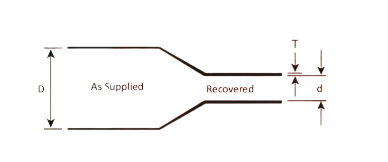
D, d and T on the manufacturer's own drawing
The drawing is the GMW 5x sheet's. The GDW sheet writes the legend out: D is the diameter as supplied, d the diameter as free recovered, T the free recovered wall. Every table below is those three quantities under different headings.
What no chart quotes is the transition the drawing shows between them. A tube caught part-way along it has neither the supplied wall nor the recovered wall, and no figure is published for anything in between.
GLC thin wall — 2:1
| Part code | Supplied ID (mm) | Recovered ID (mm) | Recovered wall (mm) | Ratio |
|---|---|---|---|---|
| GLC 6.0/3.0 | 6.0 | 3.0 | 0.56 | 2.0:1 |
| GLC 7.0/3.5 | 7.0 | 3.5 | 0.56 | 2.0:1 |
| GLC 8.0/4.0 | 8.0 | 4.0 | 0.56 | 2.0:1 |
| GLC 10.0/5.0 | 10.0 | 5.0 | 0.56 | 2.0:1 |
| GLC 12.7/6.35 | 12.7 | 6.35 | 0.56 | 2.0:1 |
| GLC 14.0/7.0 | 14.0 | 7.0 | 0.69 | 2.0:1 |
| GLC 16.0/8.0 | 16.0 | 8.0 | 0.69 | 2.0:1 |
| GLC 18.0/9.0 | 18.0 | 9.0 | 0.69 | 2.0:1 |
| GLC 20.0/10.0 | 20.0 | 10.0 | 0.78 | 2.0:1 |
| GLC 25.0/12.5 | 25.0 | 12.5 | 0.78 | 2.0:1 |
| GLC 30.0/15.0 | 30.0 | 15.0 | 0.87 | 2.0:1 |
| GLC 40.0/20.0 | 40.0 | 20.0 | 0.97 | 2.0:1 |
| GLC 50.0/25.0 | 50.0 | 25.0 | 0.97 | 2.0:1 |
| GLC 60.0/30.0 | 60.0 | 30.0 | 0.96 | 2.0:1 |
| GLC 70.0/35.0 | 70.0 | 35.0 | 1.10 | 2.0:1 |
| GLC 80.0/40.0 | 80.0 | 40.0 | 1.27 | 2.0:1 |
| GLC 100/50.0 | 100.0 | 50.0 | 1.17 | 2.0:1 |
±10% is printed on this chart's wall column, so 0.78 mm means 0.70 mm to 0.86 mm. The wall does not climb monotonically: 0.97 mm at GLC 50.0/25.0 drops to 0.96 mm at 60.0/30.0, and 1.27 mm at 80.0/40.0 drops to 1.17 mm at 100/50.0. Both steps repeat on the GLC datasheet and again on the GSC ladder below, so neither is a transcription slip.
GSC thin wall, flame retardant — 2:1
| Part code | Supplied ID (mm) | Recovered ID (mm) | Recovered wall (mm) | Ratio |
|---|---|---|---|---|
| GSC 1.0/0.5 | 1.0 | 0.5 | 0.28 | 2.0:1 |
| GSC 1.5/0.75 | 1.5 | 0.75 | 0.32 | 2.0:1 |
| GSC 2.0/1.0 | 2.0 | 1.0 | 0.35 | 2.0:1 |
| GSC 2.5/1.2 | 2.5 | 1.2 | 0.44 | 2.1:1 |
| GSC 3.0/1.5 | 3.0 | 1.5 | 0.44 | 2.0:1 |
| GSC 4.0/2.0 | 4.0 | 2.0 | 0.44 | 2.0:1 |
| GSC 5.0/2.5 | 5.0 | 2.5 | 0.56 | 2.0:1 |
| GSC 6.0/3.0 | 6.0 | 3.0 | 0.56 | 2.0:1 |
| GSC 7.0/3.5 | 7.0 | 3.5 | 0.56 | 2.0:1 |
| GSC 8.0/4.0 | 8.0 | 4.0 | 0.56 | 2.0:1 |
| GSC 10.0/5.0 | 10.0 | 5.0 | 0.56 | 2.0:1 |
| GSC 12.7/6.35 | 12.7 | 6.35 | 0.56 | 2.0:1 |
| GSC 14.0/7.0 | 14.0 | 7.0 | 0.69 | 2.0:1 |
| GSC 16.0/8.0 | 16.0 | 8.0 | 0.69 | 2.0:1 |
| GSC 18.0/9.0 | 18.0 | 9.0 | 0.69 | 2.0:1 |
| GSC 20.0/10.0 | 20.0 | 10.0 | 0.78 | 2.0:1 |
| GSC 25.0/12.5 | 25.0 | 12.5 | 0.78 | 2.0:1 |
| GSC 30.0/15.0 | 30.0 | 15.0 | 0.87 | 2.0:1 |
| GSC 40.0/20.0 | 40.0 | 20.0 | 0.97 | 2.0:1 |
| GSC 50.0/25.0 | 50.0 | 25.0 | 0.97 | 2.0:1 |
| GSC 60.0/30.0 | 60.0 | 30.0 | 0.96 | 2.0:1 |
| GSC 70.0/35.0 | 70.0 | 35.0 | 1.10 | 2.0:1 |
| GSC 80.0/40.0 | 80.0 | 40.0 | 1.27 | 2.0:1 |
| GSC 100/50.0 | 100.0 | 50.0 | 1.17 | 2.0:1 |
The same ladder as GLC from 6.0/3.0 up — identical supplied ID, recovered ID and wall, and identical spool and box quantities from 7.0/3.5 up — extended down to 1.0 mm supplied, where GLC does not go. Grade separates them: GSC is flame retardant and carries UL 224 VW-1, MIL-I-23053/5 Class 2 & 3 and CSA C22.2, and the GLC datasheet has no flammability row at all. No wall tolerance is printed on this chart. Nine of these sizes reappear on the printable marking tube Finotube, whose page carries the printing detail this one does not; that page prints GSC 25.0 / 12.0 against a 12.5 mm recovered ID, and its tenth size, GSC 12.0/6.0, survives only on an older thin-wall brochure.
GLC-SV vented — 2:1
| Part code | Supplied ID (mm) | Recovered ID (mm) | Recovered wall (mm) | Ratio |
|---|---|---|---|---|
| GLC-SV 20/10 | 20.0 | 10.0 | 0.78 | 2.0:1 |
| GLC-SV 25/12.5 | 25.0 | 12.5 | 0.78 | 2.0:1 |
| GLC-SV 30/15 | 30.0 | 15.0 | 0.87 | 2.0:1 |
| GLC-SV 40/20 | 40.0 | 20.0 | 0.97 | 2.0:1 |
| GLC-SV 45/25 | 45.0 | 25.0 | 0.97 | 1.8:1 |
| GLC-SV 50/25 | 50.0 | 25.0 | 0.97 | 2.0:1 |
| GLC-SV 60/30 | 60.0 | 30.0 | 0.96 | 2.0:1 |
| GLC-SV 70/35 | 70.0 | 35.0 | 1.10 | 2.0:1 |
GLC repeated from 20/10 to 70/35 at the same dimensions and the same packing, plus one size GLC does not carry — GLC-SV 45/25, which recovers 1.8:1 on a 2:1 series — and stopping where GLC goes on to 80/40 and 100/50. The difference is an internal air-vent groove, specified for a wrinkle-free finish over bends without grease or any other lubricant. That is why it turns up on wind-power anchor bolts and U-bolts rather than on wire.
GDW dual wall, adhesive lined — 3:1 and 4:1
| Part code | Supplied ID (mm) | Recovered ID (mm) | Recovered wall incl. adhesive (mm) | Ratio | Adhesive layer (mm) |
|---|---|---|---|---|---|
| GDW 3/1 | 3.0 | 1.0 | 0.9 | 3.0:1 | 0.35 |
| GDW 6/2 | 6.0 | 2.0 | 1.1 | 3.0:1 | 0.4 |
| GDW 8/2 | 8.0 | 2.0 | 1.2 | 4.0:1 | 0.4 |
| GDW 9/3 | 9.0 | 3.0 | 1.3 | 3.0:1 | 0.5 |
| GDW 12/3 | 12.0 | 3.0 | 1.5 | 4.0:1 | 0.6 |
| GDW 12/4 | 12.0 | 4.0 | 1.5 | 3.0:1 | 0.6 |
| GDW 16/4 | 16.0 | 4.0 | 1.8 | 4.0:1 | 0.6 |
| GDW 18/6 | 18.0 | 6.0 | 1.9 | 3.0:1 | 0.7 |
| GDW 24/8 | 24.0 | 8.0 | 2.2 | 3.0:1 | 0.8 |
| GDW 30/10 | 30.0 | 10.0 | 2.3 | 3.0:1 | 0.9 |
| GDW 39/13 | 39.0 | 13.0 | 2.4 | 3.0:1 | 0.9 |
| GDW 50/17 | 50.0 | 17.0 | 2.4 | 2.9:1 | 0.9 |
The recovered wall on this chart already includes the adhesive, so the adhesive is given separately and the polyolefin left over is the difference: GDW 39/13 recovers to 2.4 mm total, 0.9 mm of it adhesive. GDW 3/1 to 50/17 come off the 3:1 chart; 8/2, 12/3 and 16/4 off the 4:1 chart. No wall tolerance is printed.
Older GDW sheets are still in circulation and disagree
The current GDW datasheet matches the chart above row for row. Two older thin-wall sheets do not, and every row they share differs in the adhesive column. On those, GDW 18/6 recovers to 2.0 mm over 0.8 mm of adhesive rather than 1.9 over 0.7; 24/8 to 2.3 over 0.9; 39/13 to 2.5 over 1.0; 50/17 to 2.5 over 1.2. The ladders differ too: between them the older sheets carry GDW 4.8/1.6, 75/25 and 100/34, carry no 30/10, and put 100 m on a GDW 6/2 spool where the current sheet puts 50 m. None of the three is marked superseded. If the adhesive thickness is carrying your seal, say which sheet you sized from.
GDWH wire-harness dual wall — stated 4:1
| Part code | D min (mm) | d (AL) (mm) | d (J) max (mm) | Recovered wall, first column (mm) | Recovered wall, second column (mm) | Length L min (mm) |
|---|---|---|---|---|---|---|
| GDWH-1 | 5.75 | 1.25 | 2.65 | 0.60 | 0.60 | 50 |
| GDWH-2 | 7.50 | 1.65 | 3.45 | 0.70 | 1.40 | 50 |
| GDWH-3 | 11.00 | 2.40 | 4.65 | 0.80 | 1.80 | 65 |
| GDWH-4 | 14.00 | 3.00 | 5.90 | 0.90 | 2.15 | 65 |
| GDWH-5 | 18.30 | 4.35 | 7.40 | 0.90 | 2.20 | 75 |
The one series that will not normalise. It is dimensioned D, d and L rather than supplied and recovered, publishes two recovered bores per size — AL and J — and is the only series here with no datasheet among the manufacturer's 175 published sheets to check the web table against.
One heading, two wall columns, no sub-labels
In the source table Recovered Wall Thickness (min) is a single heading set over two millimetre columns, and the sub-labels that would say which bore each wall belongs to are absent. So the chart gives two recovered bores and two recovered walls per size and pairs neither. The bores are far apart — GDWH-1 is 1.25 mm on one and 2.65 mm on the other — and so is the ratio that follows: 4.2:1 to 4.7:1 across the range measured on the smaller bore, 2.2:1 to 2.5:1 measured on the larger, against a product page stating a flat 4:1. Confirm which bore and which wall apply before a harness drawing is released against a GDWH code.
GMW 5x high shrink ratio — 5:1
| Part code | Supplied ID (mm) | Recovered ID (mm) | Recovered wall (mm) | Ratio |
|---|---|---|---|---|
| GMW 5x 30/6 | 30 | 6 | 4.3 | 5.0:1 |
| GMW 5x 40/8 | 40 | 8 | 4.3 | 5.0:1 |
| GMW 5x 50/10 | 50 | 10 | 4.3 | 5.0:1 |
| GMW 5x 60/12 | 60 | 12 | 4.5 | 5.0:1 |
| GMW 5x 75/15 | 75 | 15 | 4.5 | 5.0:1 |
| GMW 5x 90/18 | 90 | 18 | 4.5 | 5.0:1 |
| GMW 5x 10⁵/21 | 105 | 21 | 5.0 | 5.0:1 |
| GMW 5x 115/23 | 115 | 23 | 5.0 | 5.0:1 |
| GMW 5x 130/26 | 130 | 26 | 5.0 | 5.0:1 |
| GMW 5x 140/28 | 140 | 28 | 5.0 | 5.0:1 |
| GMW 5x 160/32 | 160 | 32 | 5.0 | 5.0:1 |
±10% is printed on the wall column. Every row is an exact 5:1 and the wall never falls below 4.3 mm — the only series here above 4 mm at every size.
Recovered wall is measured onto nothing
Every wall figure above is taken at full free recovery: the tube shrunk down until it reaches its rated recovered ID, against no substrate at all. That is the only condition these charts publish a wall for.
Put GLC 40.0/20.0 over a 26 mm connector body and it stops at 26 mm, six millimetres short of the 20.0 mm it was measured at. Less recovery means less wall, and no chart gives a figure for any diameter between the two. Where clearance or dielectric margin depends on the wall, size so the tube lands close to its rated recovered ID, and read why shrink tube fails before accepting a large gap.
The tolerance is printed on two of the six charts. GLC and GMW 5x carry ±10%, so a quoted 0.78 mm is 0.70 mm to 0.86 mm before a substrate is anywhere near it. GSC, GLC-SV, GDW and GDWH carry none.
Whose rule the next four steps are
This site's, reconstructed from the published charts. The manufacturer publishes selection charts and nominal ratios; it does not publish a sizing procedure. Where an instruction sheet ships inside a kit, that sheet overrides everything below.
Size it as arithmetic, not as advice
Write down the largest obstruction
The biggest diameter the tube must pass over: a lug, a connector shell, a crimp, a fitted gland. Supplied ID must exceed it. By how much is a handling judgement — no clearance margin is printed on any chart above.
Write down the smallest substrate
The smallest diameter the tube has to close onto and grip. Recovered ID must finish below it. If it lands above, the tube reaches its limit while still loose, and more heat will not close the gap.
Divide, then round up to a size that exists
Largest obstruction over smallest substrate is the minimum ratio. A 34 mm lug on an 18 mm cable is 1.89, so 2:1 clears it on paper. Then check the ladder, because the ratio is necessary and not sufficient: GLC steps straight from 30.0/15.0 to 40.0/20.0, and no 36 mm size exists to take the arithmetic up on.
If both ends cannot be satisfied, change the ratio
Not the length. A longer piece of a 2:1 tube recovers to exactly the same ID as a short one. Move to GDW at 3:1 or 4:1, or GMW 5x at 5:1: recovered ID drops while supplied ID stays where the obstruction needs it. How the ratio is set covers what that does to the wall.
Worked example: a 34 mm lug on 18 mm cable
| Candidate | Supplied ID (mm) | Recovered ID (mm) | Recovered wall (mm) | Verdict |
|---|---|---|---|---|
| GLC 30.0/15.0 | 30.0 | 15.0 | 0.87 | No. Recovers well under 18 mm, but a 30 mm bore will not pass a 34 mm lug. |
| GLC 40.0/20.0 | 40.0 | 20.0 | 0.97 | No. Clears the lug, then stops at 20.0 mm, 2 mm off the cable. |
| GDWH-5 | 18.30 | 4.35 / 7.40 | 0.90 / 2.20 | No. An 18.30 mm bore will not pass the lug. |
| GDW 39/13 | 39.0 | 13.0 | 2.4 | Yes. 5 mm over the lug, and the adhesive closes at 13.0 mm. |
| GDW 50/17 | 50.0 | 17.0 | 2.4 | Yes. 16 mm over the lug, 1 mm of grip to spare. |
| GMW 5x 40/8 | 40 | 8 | 4.3 | Yes. 6 mm over the lug and recovery well past 18 mm. |
| GMW 40/12 | 40 | 12 | 2.7 | Yes. 6 mm over the lug, no adhesive lining. |
Supplied ID must clear 34 mm, recovered ID must land under 18 mm, and the verdicts are arithmetic against the ladders above rather than a manufacturer recommendation. GSC 40.0/20.0 is dimensionally identical to the GLC row and fails the same way. GDWH publishes two walls, so both are shown. GMW 40/12 comes from the medium and heavy wall range, not from a chart on this page.
Spools, boxes and the 1200 mm ceiling
Cut lengths are supplied at 1.2 m and boxed by count, and the count collapses as the tube grows. GSC runs 600 pieces at 1.0/0.5, 250 at 4.0/2.0, 65 at 20.0/10.0, 20 at 40.0/20.0 and 5 at 100/50.0; GLC joins that ladder at 6.0/3.0 with 200 and follows it down. GLC-SV runs 65 pieces at 20/10 to 10 at 70/35, the same counts as GLC over the same sizes.
Spools follow the same slope. GLC holds 100 m through 20.0/10.0, drops to 50 m from 25.0/12.5 to 40.0/20.0, and 25 m from 50.0/25.0 up. GSC matches it from 7.0/3.5 up and disagrees with itself below: one sheet puts 400 m on the six smallest sizes where another puts 200 m, and 200 m on 5.0/2.5 and 6.0/3.0 where the other puts 100 m. GDW runs 200 m down to 25 m.
One hard ceiling sits outside the thin-wall world. The medium and heavy wall sheet states a maximum available cut length of 1200 mm for the GMW and GHW series — the same 1.2 m the thin-wall boxes are already cut to. Longer than that is a conversation, not a catalogue number.
Questions the charts raise
Do I match my cable to supplied ID or to recovered ID?
Is the recovered wall in the chart what I will actually get?
Why does the recovered wall drop between two adjacent sizes?
Is GSC the same tube as GLC?
What is the largest size here, and what comes after it?
Every series above, and the page that covers it
- GLC and GSC thin wall2:1, 0.28 mm to 1.27 mm recovered wall
- GLC-SV ventedthe anchor-bolt and U-bolt case for the air-vent groove
- GDW dual wall3:1 and 4:1, adhesive included in the wall figure
- GDWH wire harnesstwo recovered bores and two walls per size
- GMW 5x5:1, 30/6 to 160/32
- GMW and GHW medium and heavy wallwhere the range goes past 160 mm supplied
- Cold shrink sizesthe same job with no torch and no recovered-wall endpoint
- Ratio, and what it costs you
Send the two diameters, not the part code
Largest obstruction, smallest substrate, length needed, and whether the joint has to seal. Those four settle the size in one exchange; a part code alone usually costs three.