Medium and heavy wall: GMW to 3.3 kV, GHW to 36 kV, 3:1
At a 22 mm bore GMW recovers with a 2.3 mm wall and GHW with 2.7 mm; at 40 mm it is 2.7 against 4.0.
Insultube GMW and GHW — medium wall and heavy wall tube
Cross-linked polyolefin, 48 published sizes from a 10 mm supplied bore to 425 mm, in two wall grades on one sheet. Manufactured by Gala Thermo Shrink Pvt. Ltd. at Palghar, Maharashtra.
- Optional hot melt adhesive for complete environmental protection and insulation, to IP68
- Halogen free
- Excellent resistance to weathering, UV rays, chemical and solvents
- Custom dimensions, thickness, length and colours available on request
- Technical Qualification Report QR 1013
| Shrink ratio | 3:1 published; the tightest printed pair, GMW 12/4, divides to exactly 3.0 |
|---|---|
| Supplied ID, GMW | 10 mm to 425 mm, 25 sizes |
| Supplied ID, GHW | 12 mm to 425 mm, 23 sizes |
| Recovered wall, GMW | 1.5 mm to 3.5 mm, ±10% |
| Recovered wall, GHW | 2.4 mm to 4.5 mm, ±10% |
| Voltage on the duty line | 3.3 kV (GMW), 36 kV (GHW) |
| Shrink temperature | 125 °C |
| Continuous temperature limit | -40 °C to +110 °C |
| Maximum cut length | 1200 mm, GMW and GHW series |
| Colour | Carbon black loaded against UV; custom colours on request |
Two duties, one chart
Medium wall is given two jobs on the sheet: environmental protection of a low voltage cable termination, and insulating the connector inside a straight-through joint or splice rated to 3.3 kV. Heavy wall is given one: mechanical protection and outer sealing of an underground straight-through joint or splice to 36 kV. Both duties are printed in that wording, and the wording is narrower than the voltage beside it.
So on an 11 kV or 22 kV joint, GMW is out on its own 3.3 kV ceiling and GHW reaches the class — but the word insulation is not on GHW's line. The grade whose duty line does carry it is the red GRT tube further down this page. Which layer sits where is set out at screening the joint; neither sheet prints an order.
Size from the two diameters, not from the code. D is the internal diameter as supplied and d the internal diameter recovered — the co-extruded and flame retardant sheets label a drawing that way, while the standard sheet calls both simply internal diameter. GMW 40/12 passes 40 mm and closes to 12 mm, and everything between is the working window. Turning an obstruction and a cable into a candidate list is arithmetic, and it is worked step by step on the size chart.
GMW medium wall selection chart
| Code | D min, supplied ID (mm) | d max, recovered ID (mm) | Wall T ±10% (mm) |
|---|---|---|---|
| GMW 10/3 | 10 | 3 | 1.5 |
| GMW 12/4 | 12 | 4 | 1.8 |
| GMW 16/5* | 16 | 5 | 2.0 |
| GMW 19/6 | 19 | 6 | 2.0 |
| GMW 22/6 | 22 | 6 | 2.3 |
| GMW 25/8 | 25 | 8 | 2.5 |
| GMW 30/8 | 30 | 8 | 2.6 |
| GMW 33/10* | 33 | 10 | 2.6 |
| GMW 40/12 | 40 | 12 | 2.7 |
| GMW 50/16 | 50 | 16 | 2.7 |
| GMW 65/19* | 65 | 19 | 2.7 |
| GMW 70/22* | 70 | 22 | 2.7 |
| GMW 75/22 | 75 | 22 | 2.7 |
| GMW 95/25* | 90 | 25 | 3.0 |
| GMW 105/30 | 105 | 30 | 3.0 |
| GMW 115/34 | 115 | 34 | 3.2 |
| GMW 130/36 | 130 | 36 | 3.2 |
| GMW 140/42 | 140 | 42 | 3.2 |
| GMW 160/50 | 160 | 50 | 3.3 |
| GMW 180/55 | 180 | 55 | 3.3 |
| GMW 200/60 | 200 | 60 | 3.5 |
| GMW 250/70 | 250 | 70 | 3.5 |
| GMW 320/90 | 320 | 90 | 3.5 |
| GMW 375/110 | 375 | 110 | 3.5 |
| GMW 425/120 | 425 | 120 | 3.5 |
Manufacturer's Medium & Heavy Wall Tubing sheet, Issue 2, July 2024, copied as printed. * marks sizes the sheet flags as new. Every other series in the range sits on the heat shrink size chart.
GHW heavy wall selection chart
| Code | D min, supplied ID (mm) | d max, recovered ID (mm) | Wall T ±10% (mm) |
|---|---|---|---|
| GHW 12/3 | 12 | 3 | 2.4 |
| GHW 19/6 | 19 | 6 | 2.5 |
| GHW 22/6 | 22 | 6 | 2.7 |
| GHW 25/8 | 25 | 8 | 2.8 |
| GHW 30/8 | 30 | 8 | 3.0 |
| GHW 33/10* | 33 | 8 | 3.0 |
| GHW 40/12 | 40 | 12 | 4.0 |
| GHW 50/16* | 50 | 16 | 4.0 |
| GHW 65/19* | 65 | 19 | 4.0 |
| GHW 70/22* | 70 | 22 | 4.0 |
| GHW 75/22 | 75 | 22 | 4.0 |
| GHW 95/25* | 95 | 25 | 4.0 |
| GHW 105/30 | 105 | 30 | 4.0 |
| GHW 115/34* | 115 | 34 | 4.0 |
| GHW 130/36* | 130 | 36 | 4.0 |
| GHW 140/42 | 140 | 42 | 4.2 |
| GHW 160/50 | 160 | 50 | 4.3 |
| GHW 180/55 | 180 | 55 | 4.3 |
| GHW 200/60 | 200 | 60 | 4.3 |
| GHW 250/70 | 250 | 70 | 4.3 |
| GHW 320/90 | 320 | 90 | 4.5 |
| GHW 375/110 | 375 | 110 | 4.5 |
| GHW 425/120 | 425 | 120 | 4.5 |
Same sheet, facing column. From 19 mm upward the two charts list the same 22 bores and the same recovered IDs, and only the wall column moves — plus GHW 12/3 at the bottom, which medium wall does not offer.
Two rows disagree with their own code
Both charts above are copied as printed, including two rows where the code and the columns do not match. GMW 95/25 is printed with D min 90 mm, while GHW 95/25 on the facing column is printed 95. GHW 33/10 is printed with d max 8 mm, while GMW 33/10 is printed 10. A third sheet takes the codes' side: the manufacturer's Red Insulation Tube chart lists the same two bores as GRT 95/25 at D min 95 and GRT(HW) 33/10 at d max 10. That is corroboration from a different document, not a correction from the manufacturer. If either size is the one your joint needs, get the diameter confirmed in writing before the code reaches a drawing or a purchase order.
What the columns divide to
3:1 is the published ratio, and the post-tensioning coupler sheet that reuses these codes prints it as high shrink ratio 3:1. Divide the two printed columns and nothing comes out under it. GMW 12/4 is exactly 3.0 and is the tightest pair in either chart; GHW 12/3 divides to 4.0, the widest once the two mismatched rows flagged above are set aside. A design worked to a flat 3:1 therefore fits every published row, with margin on most of them, and shrink ratio explained covers what that margin is worth against 4:1 and 5:1.
Wall climbs with bore on both series, and faster on heavy wall — GHW passes 4.0 mm at the 40 mm bore, where GMW is still at 2.7 and never exceeds 3.5 across the whole chart. Every wall figure carries ±10%, which at GHW 425/120 is 0.45 mm either way. Carry that into any clearance sum that assumes a finished outside diameter.
Physical properties
| Property | Value | Test method |
|---|---|---|
| Tensile strength | 12 N/mm² (MPa) (min.) | ASTM D638 |
| Ultimate elongation | 350% (min.) | ASTM D638 |
| Density | 1.0 ± 0.2 gm/cm³ | ASTM D792 |
| Longitudinal change | -10% (max.) | ASTM D2671 |
| Hardness | 45 ± 10 Shore D | ASTM D2240 |
| Water absorption | 0.5% (max.) | ASTM D570 |
Thermal properties
| Property | Value | Test method |
|---|---|---|
| Accelerated ageing | 150 °C for 168 hrs | ASTM D2671 |
| Tensile strength after ageing | 10 N/mm² (MPa) (min.) | ASTM D638 |
| Ultimate elongation after ageing | 300% (min.) | ASTM D638 |
| Low temperature flexibility, -40 °C for 4 hrs | No cracking | ASTM D2671 |
| Heat shock, 250 °C for 30 min | No cracking or flowing | ESI 09-11 |
| Shrink temperature | 125 °C | IEC 216 |
| Continuous temperature limit | -40 °C to +110 °C | IEC 216 |
Electrical properties
| Property | Value | Test method |
|---|---|---|
| Dielectric strength, 2 mm wall | 12 kV/mm (min.) | ASTM D149 |
| Volume resistivity | 1 × 10¹² Ohm.cm (min.) | ASTM D257 |
| Dielectric constant | 5 (max.) | ASTM D150 |
The datasheets and the product page give different numbers
Two datasheets print dielectric strength as 12 kV/mm minimum, qualified to a 2 mm wall — the standard sheet dated July 2024 and the flame retardant sheet dated February 2025. The manufacturer's web page for the same tube prints 15 kV/mm with no wall stated, and 10 N/mm² tensile against the 12 N/mm² both sheets carry. The tables above follow the sheets: they are dated, they tie the figure to a stated wall, and they agree with each other. Specify against 12 kV/mm at 2 mm, and ask for written confirmation if the margin is doing real work.
Not published: what carries the UV duty in a coloured tube
The weathering note under the property table says the compound contains carbon black to protect it from UV light. That is the sheet's only statement about outdoor life, and it is tied to the black compound. Custom colours are offered in the bullet directly above it, with nothing said about what replaces the carbon black in a red or grey length of the same code. On a joint that sits in an open trench before backfill, on a pole, or anywhere above ground, ask what the coloured compound was tested to and get the answer in writing.
The 1200 mm ceiling, and a code that is not unique
1200 mm is the maximum cut length published for the series, and it decides jobs. Anything needing more than 1200 mm of unbroken cover in one piece is off this chart, and two overlapped pieces are a different sealing problem. Custom dimensions, thickness, length and colour are offered on request. No price, lead time, minimum order or stock position appears anywhere on this site, because the manufacturer publishes none.
The GMW code also runs past this sheet. The post-tensioning duct coupler chart lists GMW 105/30 at the same 105 mm, 30 mm and 3.0 mm — then qualifies it differently: ageing at 120 °C for 500 hours against 150 °C for 168, volume resistivity 1 × 10¹⁴ against 1 × 10¹², adhesive lined as supplied rather than optional, 300 mm a piece rather than up to 1200, and a chart carrying on to GMW 863/250. Same code, same three dimensions, different product. Name the sheet, not just the part.
The flame retardant grade is a third chart again, not a relabelling of this one. GMW 10/4-FR recovers to 4 mm where GMW 10/3 recovers to 3, GHW 25/10-FR recovers to 10 where GHW 25/8 recovers to 8, and the range stops at 180 mm supplied instead of 425. Its ordering string puts FR where the adhesive flag goes — GMW 10/3 FR 1000, a size that sheet's own chart does not list.
INSULTUBE Red: the same bores in a different compound
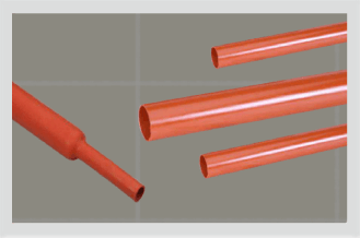
GRT is the red cross-linked polyolefin tube the manufacturer publishes for insulation in power cable joints for MV applications — the layer built up over the connector, rather than the sleeve that seals the outside. Its numbers are not the black compound's: 22 kV/mm dielectric strength against 12, volume resistivity 1 × 10¹⁴ against 1 × 10¹², water absorption 0.2% against 0.5%, and ageing at 120 °C for 500 hours instead of 150 °C for 168. Shrink temperature and continuous limit are identical, 125 °C and -40 °C to +110 °C. Halogen free, RoHS compliant, IEC 60684-3-247, Technical Qualification Report QR 1036.
The dimensions, though, are the black chart. Across the nine bores GRT publishes, every standard wall is the figure GMW prints at that bore and every heavy wall is the figure GHW prints — eighteen pairs, eighteen matches. Only GRT(EHW) at 6.2 mm has no equivalent in black. So the grade choice moves the compound and the finished outside diameter, not the fit window. No voltage class is printed on the GRT sheet at all, and nothing there maps a GRT code to a cable size; the manufacturer's own page carries the series.
GRT wall grades, against the black chart at the same bore
| Bore, D min / d max (mm) | GRT / GMW wall (mm) | GRT(HW) / GHW wall (mm) | GRT(EHW) wall (mm) |
|---|---|---|---|
| 30 / 8 | 2.6 / 2.6 | 3.0 / 3.0 | — |
| 33 / 10 | 2.6 / 2.6 | 3.0 / 3.0 | — |
| 40 / 12 | 2.7 / 2.7 | 4.0 / 4.0 | — |
| 50 / 16 | 2.7 / 2.7 | 4.0 / 4.0 | 6.2 |
| 70 / 22 | 2.7 / 2.7 | 4.0 / 4.0 | 6.2 |
| 95 / 25 | 3.0 / 3.0 | 4.0 / 4.0 | 6.2 |
| 105 / 30 | 3.0 / 3.0 | 4.0 / 4.0 | 6.2 |
| 115 / 34 | 3.2 / 3.2 | 4.0 / 4.0 | 6.2 |
| 130 / 36 | 3.2 / 3.2 | 4.0 / 4.0 | 6.2 |
Read each middle cell as the GRT wall, then the wall GMW or GHW prints at that bore. Extra Heavy Wall starts at 50/16 and has no black equivalent anywhere; an em dash means the grade is not offered at that bore. Two bores need the footnote above: the black sheet prints GMW 95/25 at D min 90 where GRT 95/25 prints 95, and GHW 33/10 at d max 8 where GRT(HW) 33/10 prints 10.
With the adhesive built in: GMWR and GHWR
GMWR and GHWR are the same two wall grades co-extruded with a hot melt adhesive lining, so the seal arrives with the tube instead of going on as mastic underneath it. The trade is dimensional and thermal. Their full selection charts, and the three manufacturer sheets that disagree about them, are on pipe corrosion protection.
| GMW | GHW | GMWR | GHWR | |
|---|---|---|---|---|
| Duty on the sheet | Environmental protection, connector insulation | Mechanical protection, outer sealing | Waterproof sealing, corrosion protection | Waterproof sealing, corrosion protection |
| Voltage class stated | To 3.3 kV | To 36 kV | None | None |
| Adhesive | Optional hot melt, to IP68 | Optional hot melt, to IP68 | Hot melt lining, supplied with | Hot melt lining, supplied with |
| Wall at a 22/6 bore | 2.3 mm | 2.7 mm | 2.0 mm | 2.5 mm |
| Largest published bore | 425 / 120 | 425 / 120 | 130 / 36 | 140 / 42 |
| Shrink temperature | 125 °C | 125 °C | Not published | Not published |
| Continuous temperature limit | -40 to +110 °C | -40 to +110 °C | -55 to +125 °C, outer wall | -55 to +125 °C, outer wall |
| Heat shock | 250 °C for 30 min | 250 °C for 30 min | 250 °C for 4 hrs, outer wall | 250 °C for 4 hrs, outer wall |
| Dielectric strength | 12 kV/mm at 2 mm wall | 12 kV/mm at 2 mm wall | 15 kV/mm | 15 kV/mm |
| Method for that figure | ASTM D149 | ASTM D149 | ASTM D2671 | ASTM D2671 |
| Qualification report | QR 1013 | QR 1013 | QR 1014 | QR 1014 |
Not published: what the adhesive itself will take
The co-extruded sheet prints no shrink temperature at all, and its property table qualifies both thermal rows to the outer wall. The temperature at which the lining flows, the temperature above which it degrades, and the recovery temperature of the finished assembly are all absent. That is the headroom traded for a built-in seal: a plain GMW or GHW tube is worked to a stated 125 °C shrink point and a -40 to +110 °C service band, while GMWR and GHWR leave the adhesive unquantified. Ask for the lining's own limits in writing before a specification commits to the co-extruded route. Ordering format on that sheet is code, size, adhesive flag, length in millimetres — GMWR 12/3 A 1000.
Where to go next
- Heat shrink size chartEvery other series on one page, sorted by recovered ID, with the sizing arithmetic worked through.
- Shrink ratio explainedWhat the spare recovery in these charts is worth, and when 4:1 or 5:1 is the honest answer.
- High shrink ratio tube, GMW 5xThe next grade up the ratio: 30/6 to 160/32, at 4.3 mm to 5.0 mm of recovered wall.
- Dual wall adhesive lined tubingThe same idea as GMWR and GHWR, at thin wall and with the adhesive layer charted.
- Semi-conductive and screening tubeWhat builds up under a GHW outer sleeve on a screened joint, innermost layer first.
- Why a recovered tube failsHalt a GHW 50/16 at 40 mm and it has spent 10 of its 34 mm of travel. The five faults, read off the part.
- The standards on this datasheet, decodedIEC 60684-3-247, ESI 09-11, IEC 216 and the ASTM methods in the tables above.
- Co-extruded tubing datasheet (PDF)The manufacturer's GMWR and GHWR charts, properties and ordering format.
Four facts settle GMW against GHW
The largest diameter the tube must pass over. The smallest it must grip. The continuous length of cover you need, against the 1200 mm ceiling. And whether the joint ends up buried, in air or in sunlight. Send those and the grade comes back in one reply, with a code that names its sheet.