GSF · GBT · splice sleeve · solder sleeve
Fibre closures, CATV taps and the seal at the cable inlet
GSF 12/4 to 75/25 closes the inlet, GBT 12/4 to 70/22 covers the tap. Both charts in full, and the row on one of them that cannot be right.
Count the seals before you count the tubes
One drop, three seals, three different diameters. The cable inlet at the base of the closure. The fusion splice, out at coating diameter. The connector on the pole or down in the pit.
No part covers all three, and the published duty lines say so. GSF is catalogued for one sentence: insulate and seal the inlet of the cable into the base of a fibre optic closure. The splice sleeve works over glass, on coating or buffer. GBT is catalogued to follow the profile of cable connectors and tap terminations.
Measure each seat separately, then read the charts. Start with the inlet — it is the only one of the three with eight published diameters behind it.
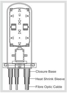
Three seals, three parts
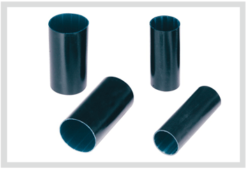
Closure inlet — GSF
INSULTUBE Commercial. Cross-linked polyolefin, adhesive lined. Eight codes, 12 to 75 mm supplied, recovering to 4 to 25 mm on a 2.0 to 3.0 mm wall, across a −40 °C to +110 °C band.
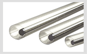
Fibre splice — splice protection sleeve
The only part here with no chart, no code list and no property table. Its whole published record is one claim: environmental and mechanical integrity restored to the fibre's coating or buffer after splicing, with no cracking, dripping or flowing under heat shock.
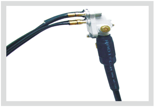
Tap and drop — GBT
INSULTUBE Premium, for underground and aerial CATV plant, CCTV connections and control-cable splicing joints. Eight codes, 12 to 70 mm supplied. Shrinks above 90 °C, holds −55 °C to +110 °C, conforms to IEC 60684-3-247.
INSULTUBE Commercial (GSF) — the closure inlet tube
Eight codes, GSF 12/4 to GSF 75/25, adhesive lined, given one job on the manufacturer's page and nothing beside it: insulate and seal the inlet of the cable into the base of a fibre optic closure.
- Hot melt adhesive gives the environmental seal onto the cable sheath
- Resistance to weathering, moisture, contamination and adverse environmental conditions
- Resistance to UV rays, ozone, chemicals and solvents
- Lightweight and flexible, and provides mechanical strain relief
- Easily re-enterable, so the closure can be opened again
| Trade name | INSULTUBE Commercial |
|---|---|
| Material | Cross-linked polyolefin |
| Supplied ID | 12 mm to 75 mm, eight codes |
| Recovered ID | 4 mm to 25 mm |
| Recovered wall | 2.0 mm to 3.0 mm, T ±10% |
| Supplied ÷ recovered, across the chart | 2.50:1 at 40/16 and 50/20, up to 3.75:1 at 30/8 |
| Continuous temperature limit | −40 °C to +110 °C |
| Shrink temperature | Not published |
| Ingress protection | IP 68, with no depth or duration stated |
| Published duty | Sealing the cable inlet at the base of a fibre optic closure |
GSF selection chart
| Code | Supplied ID (mm) | Recovered ID (mm) | Recovered wall T ±10% (mm) |
|---|---|---|---|
| GSF 12/4 | 12 | 4 | 2.0 |
| GSF 17/6 | 17 | 6 | 2.0 |
| GSF 30/8 | 30 | 8 | 2.5 |
| GSF 35/12 | 35 | 12 | 2.5 |
| GSF 40/16 | 40 | 16 | 2.5 |
| GSF 50/20 | 50 | 20 | 2.5 |
| GSF 65/22 | 65 | 22 | 2.5 |
| GSF 75/25 | 75 | 25 | 3.0 |
Copied from the manufacturer's fibre optic closure entry. It exists on that web page and in none of the 175 downloadable datasheets, so print the page when you order against it. The supplied column steps 17 straight to 30, and 50 straight to 65. GBT has a code in both holes, at 27 and at 60. Laid beside every other series, it is on the size chart.
GBT selection chart
| Code | Supplied ID, D min. (mm) | Recovered ID, d max. (mm) | Recovered wall T ±10% (mm) |
|---|---|---|---|
| GBT 12/4 | 12 | 4 | 2.0 |
| GBT 17/6 | 17 | 6 | 2.0 |
| GBT 27/8 | 27 | 8 | 2.5 |
| GBT 30/10 | 30 | 10 | 2.5 |
| GBT 40/12 | 40 | 12 | 2.5 |
| GBT 50/16 | 50 | 16 | 2.5 |
| GBT 60/20 | 60 | 20 | 2.5 |
| GBT 70/22 | 70 | 22 | 2.5 |
Copied from the manufacturer's CATV entry, which heads its two diameter columns D min. and d max. rather than supplied and recovered. Those are the better labels: supplied is a floor, recovered is a ceiling. The two series open identically at 12/4 and 17/6, then part. Three bores appear on both charts — at 30 mm GBT recovers 2 mm wider than GSF, at 40 and 50 mm it recovers 4 mm tighter. Two series, not one series printed twice.
GSF against GBT, as the two property tables print it
Same heat shock, same ageing regime, same dielectric constant. Read down the two middle columns for everywhere else.
| Property | GSF (Commercial) | GBT (Premium) | Method |
|---|---|---|---|
| Tensile strength | 11 N/mm² (min.) | 12 N/mm² | ASTM D638 |
| Ultimate elongation | 350% (min.) | 300% (min.) | ASTM D638 |
| Water absorption | 0.5% (max.) | 1% (max.) | ASTM D570 |
| Longitudinal change | −10% (max.) | −10% (max.) | ASTM D2671 |
| Tensile after 120 °C for 500 hrs | 11 N/mm² (min.) | 10 N/mm² | ASTM D638 |
| Low temperature flexibility, −40 °C for 4 hrs | No cracking | No cracking | ASTM D2671 |
| Heat shock, 250 °C for 30 min | No cracking or flowing | No cracking or flowing | ESI 09-11 |
| Shrink temperature | Not published | >90 °C | IEC 216 |
| Continuous temperature limit | −40 °C to +110 °C | −55 °C to +110 °C | IEC 216 |
| Dielectric strength | 12 kV/mm (min.) | 15 kV/mm (min.) | ASTM D149 |
| Volume resistivity | 1 × 10¹⁴ Ohm.cm (min.) | 1 × 10⁷ Ohm.cm (max.) | ASTM D257 |
| Dielectric constant | 5 (max.) | 5 (max.) | ASTM D150 |
| Conformity stated on the page | None | IEC 60684-3-247 | — |
The GBT volume resistivity row cannot be right
The CATV page prints dielectric strength at 15 kV/mm minimum and, two rows below it, volume resistivity at 1 × 10⁷ Ohm.cm maximum. A resistivity ceiling is a conductivity requirement. It specifies a screening layer, and the same wall cannot also be a 15 kV/mm insulator. The identical row, carrying the same (max..) typing slip, sits on the manufacturer's semi-conductive tube page, where it belongs; GSF, the near-twin, prints 1 × 10¹⁴ Ohm.cm minimum. Get the GBT figure confirmed in writing before that tube goes anywhere near an energised conductor. What a genuine screening spec looks like is on screening the joint.
Sizing the inlet seal
Six checks, and only the first is a pair of diameters.
- Recovered ID under the sheath OD, supplied ID over the largest thing the tube has to travel past — usually the closure spigot, not the cable.
- Do not size on a nominal 3:1. Divide the two published columns and GSF runs 2.50:1 at 40/16 and 50/20 against 3.75:1 at 30/8. Five of the eight codes fall under 3:1.
- Between a 6 mm and an 8 mm recovered bore GSF publishes nothing, and the supplied column jumps 17 to 30 across that same step. GBT 27/8 sits in that hole and GBT 60/20 in the 50-to-65 one — a different series with a different temperature band, so a substitution to confirm rather than assume.
- Recovered wall holds at 2.0 to 2.5 mm on seven of the eight codes and reaches 3.0 mm only at GSF 75/25. Wall is not the variable you buy on up here.
- Both series are published as easily re-enterable. Budget a fresh length per opening: the adhesive that made the seal is what you cut through to get in.
- IP 68 appears on both pages with no depth and no duration beside it, and IEC 60529 leaves those conditions to agreement between manufacturer and user. Ask for both before you specify a pit that floods.
Not published: any UV test behind the UV claim
GSF and GBT both claim resistance to UV rays and ozone; the co-extruded pair claims resistance to UV rays. None of the three carries a UV row in its property table — no exposure hours, no weathering method, no retained-property figure. The manufacturer does publish one, on a different product: the polyolefin overhead line cover is qualified at 5000 hours to ASTM G154 with no colour change. The test exists in the house and has not been run onto these. Buried, the gap costs nothing. On an aerial span in direct sun it is the service life, so ask for the weathering data before the order goes out.
The solder sleeve is a sequence, not a tube
Terminating the braid on a coaxial drop is a different device again. Three transitions run on one heat cycle inside a solder sleeve: the radiation cross-linked polyolefin sleeve recovers, the solder preform with flux to ANSI/J-STD-006 melts onto the shield, and a thermally stabilised thermoplastic ring melts and seals at each end. The manufacturer names the material of all three and the temperature of none, so nothing published tells you the order they happen in. The failure that hides is a cold joint under a sleeve that looks finished from outside.
Two published figures do gate its use. The cable insulation must be rated for at least +85 °C, written as a condition rather than a preference, and the device itself is given −55 °C to +125 °C. Seven sizes run GSS-3 to GSS-13, ØA 2.50 mm to 13.00 mm minimum, every letter defined on the drawing beside the solder sleeve listing. It has no place on a fibre splice: a solder sleeve terminates a metal shield and a fusion splice has none.
What the cold shrink range here is actually catalogued for
Cold shrink communication tubing is a real search, and this range does not answer it. The published cold shrink tube is GCTE: an EPDM sleeve factory-expanded onto a removable core, seven sizes from GCTE 20/7 to GCTE 104/42, an 8 to 94 mm application range, catalogued for inline connections and terminal lugs on copper and aluminium conductor up to 1100 V.
Every line of that brief is a power brief, and none of it names a coaxial drop, a tap or a closure inlet. On this job the published answer is heat shrink. The GCTE chart and the application-range column that goes with it are on cold shrink tubing; where the elastic route stops is on cold shrink.
Buried, flooded or backfilled: move to the heavier pair
GSF and GBT already carry hot melt, so the reason to move is wall, not sealing. Where a tap sits in a pit that floods, the manufacturer prints the same three CATV lines again on a heavier product: GMWR and GHWR repeat underground and aerial CATV plant connections, CCTV connections and control-cable splicing joints word for word, under Technical Qualification Report QR 1014 and conforming to IEC 60684-3-247. Wall reaches 4.2 mm against GBT's 2.5 mm ceiling.
Order that pair carefully. The manufacturer's own sheets do not agree on the co-extruded charts, and the disagreement reaches the wall figure at 12 mm supplied — set out at pipe corrosion protection. Quote the sheet revision beside the code. The wall grades themselves are on medium and heavy wall tubing, the adhesive layer on dual wall tube.
Next
- Heat shrink size chartGSF and GBT beside every other series on one axis
- Medium and heavy wall tubingGMWR and GHWR for a tap that sits under water
- Installing heat shrink tubeGun distance and stroke order on a 2.5 mm wall
- Why a recovered tube failsBridged wall, unflowed adhesive, and the three faults after them
- The standards on a shrink tube datasheetWhat IEC 60684-3-247, ESI 09-11 and ASTM D2671 each test
Send the sheath OD and the connector's widest point
Sheath OD where the tube lands, the largest diameter it has to pass, aerial or buried, and whether it will ever be re-entered. Four answers pin a GSF or GBT code in one reply.